I am repairing my failed TIG welder and a shorted choke coil (called a reactor in some regions) has been rewound. Out of circuit testing of the two high amperage SCR's shows them good, but I am having issues where I believe on DC setting the output is not being rectified correctly. It may be a control circuit issue, or a phasing issue of the new choke. I would like to look at the trigger signals to the gates of the SCR's. The circuit is hopefully attached, if not it can be seen at
http://www.gatesgarth.com/schematic.jpg There is also a function description from the user manual as a jpg at
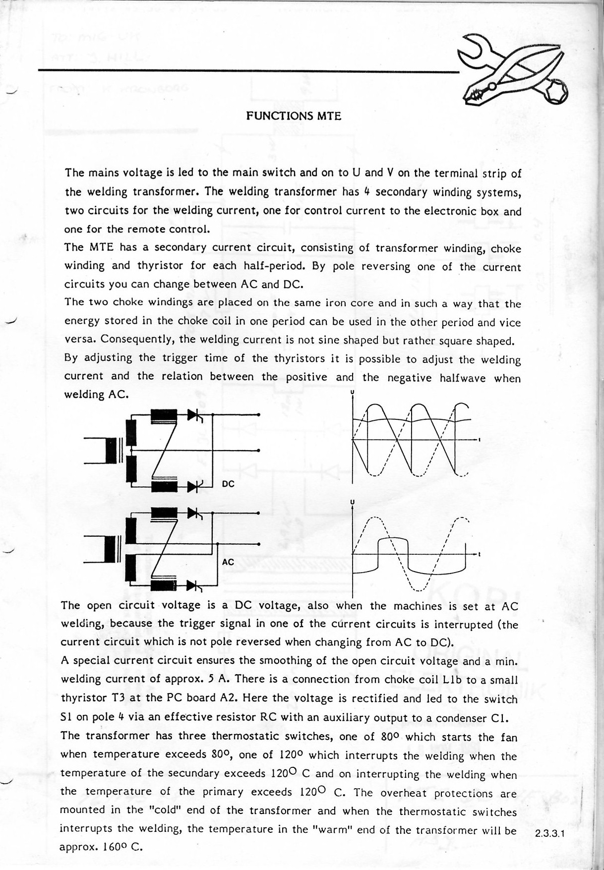
http://www.gatesgarth.com/function-description.jpg I have both a conventional mains powered dual channel scope, and more usable given portability, a 200MHz USB dual channel scope that I can run on my laptop, fully isolated from the mains> I do believe the transformer coupling in the single phase TIG welder should preclude ground loop issues, however?
I need to know where is best to take the ground lead of the probe to, chassis ground, or the cathode of the SCR, and what sort of trigger pattern one might expect to see. Thanks.

- schematic.jpg (212.8 KiB) Viewed 6481 times


