


Hi All
I want to build a circuit that when pulsed with 12 volt DC will operate a relay, and hold it operated until the receipt of another pulse, at this point the relay should be released and a second relay energised and held energised until receipt of a third pulse. The pattern could then be repeated.
I've just read this back and it would probably have been easier to explain what I am trying to do, I want to be able to select the output from three cameras at the rear of my caravan and connect to a 2.5 meg. transmitter mounted at the rear of the caravan, with the receiver connected to a monitor in my car. I would only ever want to select a different camera if I were stationary so I could pulse the control unit with the rear fog light switch, therefor negating the need for any hard wiring from car to caravan. I am capable of building a circuit having worked in electronics (a very long time ago) but need the technical information.
Sequential relay operation

Re: Sequential relay operation
Is this what you want?:

If you want to install the ON/OFF switch then what do you want to happen when the circuit is powered off and on again? No relays activated, relay 1 activated, or the same relay activated as before the circuit was powered off?
If you want to install the ON/OFF switch then what do you want to happen when the circuit is powered off and on again? No relays activated, relay 1 activated, or the same relay activated as before the circuit was powered off?
Re: Sequential relay operation
Hi Thomas thanks for replying
Yes that is what I am after, except that the 12 volt supply is controlled by the vehicle ignition, (via the refrigerator supply)
Assume that relay 1 is energised when the engine is started, it would stay energised until such time that camera 2 or 3 was needed.
Switching the fog light on briefly would release relay 1 and energise relay 2 leaving it energised until such time that either 3 or 1
is needed.
Or in a nutshell, every on/off operation of the fog light switch, energises the next relay, and releases the previous ad infinitum.
My problem is what goes on in the box you have marked 'Control Circuit'.
Thanks again and here's hoping.
JAH
Re: Sequential relay operation
Updated system diagram:

Here's an idea for the control circuit:

Just make sure that the voltage from Rear fog light doesn't exceed +12VDC from refrigerator with more than 0.5 volts, or else you'll need a voltage divider on IC1 pin 14 to lower the voltage in order to protect the IC.
The types of diodes, resistors and transistors depends on what relays you're using.
Avoid static discharge when handling the IC.
Here's an idea for the control circuit:
Just make sure that the voltage from Rear fog light doesn't exceed +12VDC from refrigerator with more than 0.5 volts, or else you'll need a voltage divider on IC1 pin 14 to lower the voltage in order to protect the IC.
The types of diodes, resistors and transistors depends on what relays you're using.
Avoid static discharge when handling the IC.
Re: Sequential relay operation
Hi Thomas
Thanks for your help so far, but I’m afraid I need more. I have no idea how to work out the values of components used in the circuit you have drawn. From what I have read on Maplins web site, due to the high resistance of a reed relay (1050ohms for their 12 volt SPST version) it would be possible for the IC to drive the relays without the need for transistors, would you agree with that, if this is possible it would be much easier to work out the connections on veroboard.
I haven’t been able to find the exact IC you specified, could you suggest an alternative.
I would be grateful for your further assistance.
Regards JAH
Re: Sequential relay operation
I assume the relay you have found is this one:
http://www.maplin.co.uk/sealed-reed-rel ... cification
The coil current is 11.4 mA at 12 VDC.
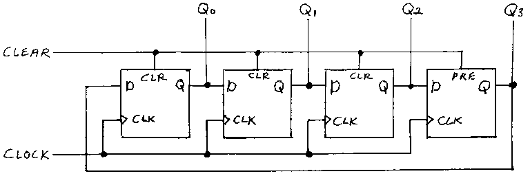
I can not find the 4017 IC at Maplin either, but it should be possible to build an Overbeck ring counter from two 4013 IC's instead:
http://en.wikipedia.org/wiki/Ring_counter
http://www.charlespetzold.com/code/Walk ... ounter.png
http://www.maplin.co.uk/cmos-logic-hcf- ... ries-31820
When I look in a datasheet for a 4013 IC I find the maximum current to be around 3 mA, which would not be enough to feed the coil:
http://en.wikipedia.org/wiki/List_of_40 ... d_circuits
http://www.maplin.co.uk/sealed-reed-rel ... cification
The coil current is 11.4 mA at 12 VDC.
I can not find the 4017 IC at Maplin either, but it should be possible to build an Overbeck ring counter from two 4013 IC's instead:
http://en.wikipedia.org/wiki/Ring_counter
http://www.charlespetzold.com/code/Walk ... ounter.png
http://www.maplin.co.uk/cmos-logic-hcf- ... ries-31820
When I look in a datasheet for a 4013 IC I find the maximum current to be around 3 mA, which would not be enough to feed the coil:
http://en.wikipedia.org/wiki/List_of_40 ... d_circuits
Re: Sequential relay operation
Updated circuit:
http://diagramtips.com/images/2011/caravan_cameras.png
T4, C1, R4 and R5 should be able to reset the ring counter properly, to make sure only one relay is ON at a time.
http://diagramtips.com/images/2011/caravan_cameras.png
T4, C1, R4 and R5 should be able to reset the ring counter properly, to make sure only one relay is ON at a time.